How to choose a LED lamp driver: types, purpose + connection features

LED lamps have become widespread, as a result of which the active production of secondary power sources has begun. The driver of the LED lamp is able to stably maintain the set current values at the output of the device, stabilizing the voltage passing through the chain of diodes.
We will tell you all about the types and principles of operation of the current conversion device for the operation of a diode lamp. In our article, we provide guidance on choosing a driver, and give useful recommendations. We will find independent home electricians with proven connection schemes.
The content of the article:
Purpose and scope of use
Diode crystals consist of two semiconductors - the anode (plus) and the cathode (minus), which are responsible for the transformation of electrical signals. One area has P-type conductivity, the second - N. When a power source is connected, current will flow through these elements.
Due to this polarity, the electrons from the P-type zone rush to the N-type zone, and vice versa, the charges from the N point rush to P. However, each section of the region has its own boundaries, called P-N junctions. At these sites, particles are found and mutually absorbed or recombined.

During P-N junctions, the voltage decreases by a certain number of volts, always the same for each element of the circuit. Given these values, the driver stabilizes the incoming current and forms a constant value at the output.
What power is required and what values of losses during P-N passage are indicated in the passport of the LED device. Therefore, for choosing a diode bulb it is necessary to take into account the parameters of the power supply, the range of which should be sufficient to compensate for the lost energy.

Power supplies with voltage from 10 to 36 V are used to equip lighting devices.
The technique can be of various types:
- headlights of cars, bicycles, motorcycles, etc .;
- small portable or street lights;
- led lighttapes ceiling light and modules.
However for low power leds, as well as in the case of using constant voltage, drivers are permissible not to apply. Instead, a resistor is also introduced into the circuit, also powered by a 220 V.
The principle of operation of the power supply
Let’s figure out what the differences are between the voltage source and the power supply. As an example, consider the circuit shown below.
By connecting a 40 ohm resistor to the 12 V power supply, a current of 300 mA will pass through it (Figure A). With the parallel connection of the second resistor in the circuit, the current value will be - 600 mA (B). However, the voltage will be unchanged.

Now we will consider how the values will change if resistors are connected to the power supply in the circuit. In the same way, we introduce a 40 Ohm rheostat with a 300 mA driver. The latter creates a voltage of 12 V on it (circuit B).
If the circuit is composed of two resistors, then the current value is unchanged, and the voltage is 6 V (G).

Drawing conclusions, we can say that a high-quality converter supplies the load with a rated current even when the voltage drops. Accordingly, crystals of diodes of 2 V or 3 V and a current of 300 mA will burn equally bright with a reduced voltage.
Distinctive characteristics of the converter
One of the most important indicators is the transmitted power under load. The device must not be overloaded and try to get the highest possible results.
Improper use contributes to the rapid failure of not only the overview mechanism, but also LED chips.
The main factors affecting work include:
- constituent elements used in the assembly process;
- degree of protection (IP);
- minimum and maximum values at the input and output;
- manufacturer.
Modern models of converters are available on the basis of microcircuits and apply the technology of pulse-width transform (PWM).

Such devices are characterized by a high degree of protection against short circuits, network congestion, and also have increased efficiency.
Rules for selecting a current converter
To purchase a LED lamp converter, you should study the key device characteristics. It is based on the output voltage, rated current and power output.
Light diode power
We will analyze the output voltage initially, which is subject to several factors:
- the value of voltage losses at the P-N junction of crystals;
- the number of light diodes in the chain;
- wiring diagram.
The parameters of the rated current can be determined by the characteristic features of the consumer, namely the power of the LED elements and their degree of brightness.
This indicator will affect the current consumed by the crystals, the range of which varies based on the required brightness.The task of the converter is to provide these elements with the supply of the right amount of energy.

The power of the device depends on the strength of each LED element, their color and quantity.
To calculate the energy consumed, use the following formula:
PH = PLED * N,
Where
- PLED - electric load created by one diode,
- N is the number of crystals in the chain.
The obtained indicators should not be less than the driver power. Now you need to determine the required nominal value.
Maximum power of the device
It should be borne in mind that in order to ensure stable operation of the converter, its nominal parameters must exceed the obtained P value by 20-30%H.
Thus, the formula takes the form:
Pmax ≥ (1,2..1,3) * PH,
where pmax - rated power of the power supply.
In addition to the power and number of consumers on the board, the load force is also subordinate to the color factors of the consumer. At the same current, depending on the shade, they have different indicators of voltage drop.

Take for example, the LEDs of the American company Cree from the XP-E line in red.
Their characteristics are as follows:
- voltage drop 1.9-2.4 V;
- current 350 mA;
- average power consumption 750 mW.
An analog of green color at the same current will have completely different indicators: losses on P-N junctions are 3.3-3.9 V, and power is 1.25 W.
Accordingly, it can be concluded: a driver rated at 10 watts is used to power twelve red crystals or eight green ones.
LED connection diagram
The choice of driver should be made after determining the connection scheme of LED-consumers. If you first buy light diodes, and then select a converter for them, this process will be accompanied by a lot of difficulties.
To search for a device that ensures the operation of just such a number of consumers with a given connection scheme, you will have to spend a lot of time.
Let's give an example with six consumers. They have a voltage loss of 3 V, a current consumption of 300 mA. To connect them, you can use one of the methods, while in each case the required parameters of the power supply will differ.

In our case, a serial connection requires an 18 V unit with a current of 300 mA. The main advantage of this method is that the same force passes through the entire line, respectively, all diodes burn with identical brightness.

If parallel placement is used, it is enough to use a 9 V converter, but the current consumption will be doubled in comparison with the previous method.

If you use a sequential method with the formation of pairs of two LEDs, a driver with the same indicators is used, as in the previous case. In this case, the brightness of the lighting will already be uniform.
However, here there were some negative nuances: when power is supplied to the group, due to the dispersion of characteristics, one of the LEDs can open faster than the second, and accordingly, a current that doubles the rated value will go through it.
Many species LEDs for home lighting designed for such short-term leaps, but this method is less popular.
Types of drivers by device type
Devices that convert 220 V power supply to the necessary indicators for LEDs are conventionally divided into three categories: electronic; based on capacitors; dimmable.
The market of lighting accessories is represented by a wide variety of driver models, mainly from a Chinese manufacturer. And despite the low price range, from these devices you can choose a very decent option. However, you should pay attention to the warranty card, because not all products presented are of acceptable quality.
Electronic view of the device
Ideally, the electronic converter should be equipped with a transistor. Its role is to discharge the control chip. To eliminate or maximize smoothing of the ripple, a capacitor is mounted at the output.
This type of device belongs to an expensive category, but it is able to stabilize the current up to 750 mA, which ballast mechanisms are not capable of.

Pulsation is not the only disadvantage of converters. The second can be called electromagnetic interference of the high-frequency (HF) range. So, if other electrical appliances, for example, radio, are connected to the outlet connected to the lamp, you can expect interference when receiving digital FM frequencies, television, a router, etc.
An optional device of a high-quality device should have two capacitors: one is electrolytic for smoothing ripples, the other is ceramic, for lowering the RF. However, such a combination can be found infrequently, especially if we talk about Chinese products.

Due to the high efficiency (up to 95%), such mechanisms are suitable for powerful devices used in various fields, for example, for tuning cars, in street lighting fixtures, as well as household LED sources.
Capacitor based power supply
Now we turn to not so popular devices - based on capacitors. Almost all of the low-cost LED lamp circuits that use this type of driver have similar characteristics.
However, due to modifications by the manufacturer, they undergo changes, for example, the removal of any element of the chain. Especially often this part is one of the capacitors - smoothing.

Such mechanisms have only two advantages: they are available for self-assembly, and their efficiency is equal to one hundred percent, since losses will only occur at p-n junctions and resistances.
The same number of negative aspects: low electrical safety and a high degree of ripple. The second drawback is about 100 Hz and is formed as a result of rectification of an alternating voltage. The state standard specification spells out the norm of permissible ripple of 10-20% depending on the purpose of the room where the lighting device is installed.
The only way to smooth this shortcoming is to select a capacitor with the correct rating. Nevertheless, you should not count on a complete elimination of the problem - such a solution can only smooth out the intensity of the bursts.
Dimmable Current Converters
Drivers dimmers for dimmable LED bulbs allow you to change the incoming and outgoing current indicators, while reducing or increasing the degree of brightness of the light emitted by the diodes.
There are two connection methods:
- the first involves a soft start;
- the second is pulsed.
Consider the principle of operation of dimmable drivers based on the CPC9909 chip used as a regulating device for LED circuits, including those with high brightness.

With a smooth start, the driver chip provides a gradual inclusion of diodes with increasing brightness. For this process, two resistors are used, connected to the LD terminal, designed to perform the task of smooth dimming. This implements an important task - extending the life of LED elements.
The same conclusion is also provided by analog regulation - a 2.2 kΩ resistor is changed to a more powerful variable analog - 5.1 kOhm. Thus, a smooth change in the output potential is achieved.
The application of the second method involves the supply of rectangular pulses to the low-frequency output PWMD. This involves either a microcontroller or a pulse generator, which are necessarily separated by an optocoupler.
With or without housing?
Drivers are available in or without housing. The first option is the most common and more expensive. Such devices are protected against moisture and dust particles.
Devices of the second type are used for flush mounting and, accordingly, are cheap.

Each of them is distinguished by an allowable temperature during operation - it is also necessary to pay attention to this when selecting.
Classic driver circuit
For self-assembly of the LED power supply, we will deal with the most simple device of a pulse type that does not have galvanic isolation. The main advantage of this type of circuit is its simple connection and reliable operation.

The scheme of such a mechanism is composed of three main cascading areas:
- Capacitive voltage separator.
- Rectifier.
- Surge Protectors.
The first section is the counteraction exerted by alternating current on capacitor C1 with a resistor. The latter is required solely for independent charging of the inert element. It does not affect the operation of the circuit.

When the formed half-wave of voltage passes through the capacitor, the current flows until the plates are fully charged. The smaller the capacity of the mechanism, the less time will be spent on its full charge.
For example, a device with a volume of 0.3-0.4 μF is charged for 1/10 of the half-wave period, i.e., only a tenth of the transmitted voltage passes through this section.

The second cascade is an electrical device that converts (rectifies) alternating current into pulsating. This process is called half-wave. Since one part of the half-wave was smoothed by a capacitor, at the output of this section, the direct current will be 20-25 V.

The third cascade operates on the basis of a smoothing stabilizing filter - an electrolytic capacitor. The choice of its capacitive parameters depends on the load.
Since the assembled circuit reproduces its work immediately, it is impossible to touch the bare wires, since the conducted current reaches tens of amperes - the lines are preliminarily insulated.
Conclusions and useful video on the topic
All the difficulties that a radio amateur may encounter when choosing a converter for high-power LED lamps are described in detail in the video:
Key features of independent connection of the converter to the electrical circuit:
Step-by-step instruction describing the DIY assembly process of the LED driver from improvised means:
Despite the manufacturer's tens of thousands of hours of uninterrupted operation of LED lamps, there are many factors that significantly reduce these indicators.
Drivers are designed to smooth out all current surges in the electrical system. Their choice or self-assembly must be approached responsibly after calculating all the necessary parameters.
Tell us how you selected the driver for the LED bulb. Share your arguments and ways to stabilize the supply of voltage to a diode lighting device. Leave comments in the block below, ask questions, post photos on the topic of the article.
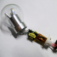 LED lamp layout: simple driver device
 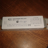 Ballast for fluorescent lamps: why is it needed, how it works, types + how to choose
  Inductor for fluorescent lamps: device, purpose + circuit for connecting
 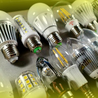 LED lamp bases: types, marking, technical parameters + how to choose the right one
 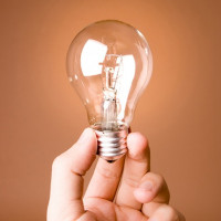 Incandescent lamps: types, specifications, how to choose the right
 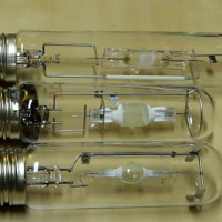 Metal halide lamps: types, device, pros and cons + selection rules
  How much does it cost to connect gas to a private house: the price of organizing gas supply
  The best washing machines with dryer: model rating and customer tips
  What is the color temperature of light and the nuances of choosing the temperature of the lamps to suit your needs
  Replacement of a geyser in an apartment: replacement paperwork + basic norms and requirements
The driver is needed to stabilize the voltage and maintain the output current value. When buying, you need to start from the parameters of the power supply. But if the LEDs in the device are low-power, a driver is not needed. Then a resistor is included in the circuit.
The drivers we sell are mainly made in China (as well as most of the rest). Prices for such drivers are low, and the quality is bearable.