How to connect a passage switch: circuit analysis + step-by-step connection instructions

Pass-through switch - the very name of this type of electrical device already shows their true purpose. Devices belong to the family of standard household switches, familiar to all owners of residential real estate.
Actually, the design of the devices resembles a traditional design. The only difference is how to connect the passage switch, the contact group diagram of which is somewhat different.
Let's see together what rules should be followed when connecting a pass-through switch, and what actions should be discarded.
The content of the article:
Feed Through Switches
Convenience and practicality of this type of devices are obvious. Electric networks equipped with such communicators are operated more efficiently, as in the end, energy savings are actually observed.
For example, to go through a long corridor at the entrance, the lighting is turned on, and the output is turned off. This function is implemented by only two devices mounted at different ends of the corridor.

If we compare the design with a conventional on / off device, the difference is noted in the number of working contacts of the devices. The design of a simple switch provides only the closing / opening of two contacts.
The wiring of the passage switch involves the creation of three working lines, one of which is common, and the other two are cross over. So it becomes possible to control a section of the electric circuit from various points.
All subtleties of choice and types of passage switches are described here.
The principle of operation of the single-key model
Actually, the principle of the function looks simple and straightforward.The overload contacts existing in the structure in the first position close one segment of the circuit and open the other, and in the second position of the override contacts the circuit is inverted.

On the case of each branded switch there is always a schematic diagram of its connection. For example, the user has a single-key device. It is necessary to include it in a simple control circuit for a single lamp.
Detailed installation instructions for the single-key switch are presented in this stuff.
If we turn to the installation scheme of a single-button walk-through switch, which is contained on its case, the user’s actions are as follows:
- On the first (C) contact, a common line is connected.
- On the second (P) and third (P) contacts fail over the cross over segments.
- Install two devices at previously designated points.
The numbering changeover contacts (P) of the two switches, identical in numbering, are connected to each other by conductors. The first (common - Common) contacts of the two devices are connected - one with a phase wire, the second with a "zero" through the lamp lamp.
The operation of the circuit is tested as follows:
- Mounted section of the circuit provide voltage.
- Switch the key of the first switch to the "On" mode.
- The lamp lights up.
- Follow to the point of placement of the second device.
- Change the current key position of the second device.
- The light lamp turns off.
Now, if you do all the operations in the reverse order, the effect of the lighting system will be similar. So the normal operation of the circuit is ascertained.
How to perform a real installation?
Before you begin installing an apartment (or other) walk-through switch, it is recommended to draw a wiring diagram, something like this:

The current supply to the circuit section with passage switches, as a rule, is carried out through a standard junction box. Thus, the first installation step is the selection of the optimal place for the junction box, its installation and the supply of electrical wiring. The cable is put into the box with a three-core cable (phase-zero-ground).
In addition to the installation of the junction box, there remains a natural need for the preparation of niches for mounting the chassis of the passage switches. The most convenient places are also chosen for them. Usually mount devices next to the boxes of passage doors.

Having completed the preparatory installation procedures, they proceed to connect the divorced conductor lines. The first is connected to any of the switches, to its 1 output (phase conductor).
Next, conduct the connection of conductors between the changeover contacts. The last is the zero line connected to the first contact of the second switch that is free. It remains to bring the voltage to the assembled circuit (turn on the circuit breaker) and test the assembly for correct operation.
Cross Designs
There is a modification of devices - cross switches. Structurally, they are devices with switching to four contacts. Their main purpose is to help in the construction of switching schemes for fixtures and other devices from three or more control points.

Meanwhile, for the implementation of such schemes with the participation of cross-models in the structure, it is required to use ordinary pass-through switches. The circuit implementation involves the inclusion of cross-wise modifications sequentially between a pair of conventional walk-through switches. The cross model has a pair of input and a pair of output terminals.
Read about the intricacies of installing cross circuit breakers Further.
Products for external (surface) mounting and devices for use in hidden wiring networks are produced. There is a wide selection of load capacities, and a variety of colors and designs also does not limit user needs.
Circuit solutions for practical use
The most commonly used circuits with connecting devices of continuous operation are, as a rule, circuits for one-, two-, three keys appliances. The one-key option was considered above.

Therefore, we will see how step-by-step instruction on connecting a two-key device looks like.
- It is necessary to outline the installation of the system.
- Perform work on the installation of the Republic of Kazakhstan and the sockets.
- Install the desired number of light groups.
- Lay the network taking into account the connection of phase, zero, grounding conductors.
- Connect the diluted conductors according to the circuit diagram.
Attention should be paid not only to purely electrical work, but also to the technical plan. For example, it is recommended to pay great attention to the installation of socket boxes.
These elements must be securely mounted in the wall, so that subsequently they provide no less reliable fastening of the devices.
There is a three-point communication system, which is based on the creation of a system that allows you to control a light group of three points separated at distances. Elemental base - three devices, of which two are double key and one cross.

A peculiar connection instruction in this case looks something like this:
- A wiring and exclusion scheme is created.
- Work is being done on the installation of the distribution box and socket boxes.
- 4 electric three-core cables are laid.
- Wiring is carried out - connection according to the scheme.
This option for creating a communications network looks somewhat complicated. As you know, even in cable management, you have to deal with a total of 12 conductors. 6 conductors should be connected to ordinary pass-through switches, while 8 conductors should be connected to the crossover switch.
A phase line is connected to the common terminal of any of the two-gang switches. A line of the light group is connected to the common line of the second two-gang switch. The remaining conductors are connected by pin numbers according to the circuit layout.
Touch models of switches
In addition to keyboard and lever modifications on the market there are models of touch performance. In fact, the functions of the devices are monotonous, but the principle of operation, as well as the design, are slightly different.

There are two types of touch switches:
- Touch direct action.
- Touch with dimmers.
The former work on direct clear contact through a short touch of a fingertip on the glass panel of the device. That is, in this embodiment, only the on / off function is valid. The second constructive option (dimmer) provides switching on and off with smooth regulation of the brightness of the lamps.
To work with these devices, the same finger touch is required, followed by holding the finger pads on the glass until the desired brightness of the lamp glow is reached.

The circuitry of sensor devices differs from other devices in that it contains one common (phase) terminal (L), two change-over (L1, L2) and one “COM” terminals.
Contact "COM" is used for communication between switches in the construction of complex circuits. For example, with control of three or more points by several lighting zones. In this case, a load power of not more than 1 kW is allowed per one light zone.

Simple organization of a control system with one touch device is as follows:
- The phase line is connected to the “L” terminal.
- Line “L1” forms one lighting zone.
- Line "L2" forms a second lighting zone.
If a group of devices is used, the phase contacts of the devices (L) are connected in parallel, plus the COM terminals are connected to each other. All other terminals are switched off as standard depending on the number of switched light zones.
In order for the touch devices to function correctly, they must be programmed. In fact, we are talking about the synchronization of all the circuit breakers. Programming is performed by the sequence:
- Touch the sensor for 5 seconds. before a sound signal (or a blinking LED).
- After the beep, remove the touch and go to the next device.
- Touching the sensor of the second device.
- If the LED on the front panel responded with short flashes, successfully.
- Cancel synchronization - touch the sensor for 10 seconds.
For sensor designs, there are some installation restrictions.
For example, the maximum permissible distance from the circuit breaker to the circuit breaker should be at least 30 m.
We also recommend that you read our other article, where we talked in detail about touch light switches, their varieties and labeling.
Conclusions and useful video on the topic
Theoretical information on how the installation of a passage switch in a room occurs:
These are the seriously modified electrical components that electrical switches familiar to all look like. Now these are no longer just switches of light bulbs screwed into the lampholders.
These devices can be successfully used to control other objects. For example, performing work on raising and lowering the curtains on the windows of the apartment.
If you had to independently install a passage switch in your own home, please share your experience with our readers. Tell us how you implemented this task in practice. Leave your comments in the box below. There you can ask questions about the topic of the article, and we will try to respond to them promptly.
 How to connect a double switch to two bulbs: schemes + connection tips
 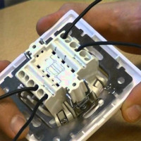 Connecting the passage switch from two and three places: analysis of circuits + installation instruction
 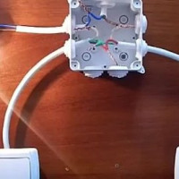 How to choose a passage switch: device and purpose of various types + marking
 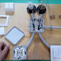 Two-way walk-through switch: device + wiring diagram + installation tips
  How to connect a dimmer: possible schemes + instructions for connecting with your own hands
  How to connect an LED switch: rules for connecting a backlit switch
  How much does it cost to connect gas to a private house: the price of organizing gas supply
  The best washing machines with dryer: model rating and customer tips
  What is the color temperature of light and the nuances of choosing the temperature of the lamps to suit your needs
  Replacement of a geyser in an apartment: replacement paperwork + basic norms and requirements
A bit of Russian: a passage switch is more correctly called a switch. Since it does not happen in the open state, it switches the current from one contact to another. Such systems are mounted in long corridors, on flights of stairs and when lighting alleys. To insert cross-switches there, in my opinion, is not justified. And the touch switch is not a topic at all.
I am having a problem with pass-through switches. The situation is the following - they are installed in a country cottage and it is worth screwing in energy-saving light bulbs, they begin to flicker. In this case, ordinary incandescent bulbs work fine. There are no LEDs or other lights in the switches themselves. I checked these flickering bulbs in another place - they work fine. What can be wrong?
Hello. The problem is quite typical for LED lamps, but the point here may not only be in the type of switch. First of all, the cause of the flashing LED lamp when the state is off may be an incompletely open circuit. There are two reasons: errors during wiring and low-quality circuit breaker.
We are talking about a switch with LED backlight, because of which the electric circuit does not open to the end, since the LED for illumination closes the circuit to itself. In this case, the elementary replacement of the circuit breaker with a better model will help to fix the problem. In the case of problems in the wiring, you will have to systematically examine each section to find the cause.
It often happens that the cause of blinking when turned off is the LED lamp itself. Often this is observed in budget models of little-known manufacturers.