Two-way walk-through switch: device + wiring diagram + installation tips

To save on electricity in the walk-through rooms will help the two-key walk-through switch (DPV). This device provides equal control of light devices from several places, making the process more comfortable.
When installing DPV, it is important to correctly plan the placement of wiring, based on the geometry of the room. Let’s take a look at the features of connecting two-gang push-button switches
The content of the article:
Purpose and types of passage switches
The essence of passage switches (PV) is the ability to turn on and off the lamps independently from several places. Therefore, the scheme of operation of this equipment implies the presence of at least two circuit breakers.
By functionality, household walk-through switches can have from 1 to 3 keys, each of which is an independent adjusting mechanism.

Different switch toggle switches control different circuits of lighting fixtures, therefore, specifically DPV are designed for chandeliers or shades with two electrical circuits.
With an increase in lighting control points, the number of wires participating in the circuit increases sharply. Because of this, in home wiring, mainly two or three pass-through switches for one lamp are used.
The PV interface can be divided into:
- mechanical;
- sensory;
- remote.
The latter are rarely used due to impracticality, but you can find them in stores. Touch switches are good in that any touch to them leads to alternately turning on or off the light. Mechanical keys are more familiar to humans and allow you to tactilely feel the change in the position of the toggle switch.

The visual performance of the DPA can be very diverse. In electrical equipment stores, you can select the passage switches of the desired color, shape and design. External parameters of the device do not affect its functionality.
Preferential Locations
Feed-through switches are installed in any places accessible to hands. It is not necessary to constantly use both devices to control the light. The main can be one switch, and the second can only be used if necessary.

Mostly DPV are installed in such places:
- At the opposite ends of a long corridor. If there is an additional door in the middle, then you can also place a limit switch near it.
- In large bedrooms. One DPV can be placed classically on the wall near the door, and the other on the bed.
- On the flights of stairs.
- On the paths and paths of houses, cottages, cottages. It is convenient to leave the house in the evening, walk along the illuminated alley and turn off the light near the entrance gate.
- In large halls with several entrance doors on opposite sides.
The pass-through switch simultaneously saves energy and ensures the safety of movement of people. The only disadvantage of this device is the increased complexity and cost of the initial installation.
DPV device and working circuit
The passage switch is rather called a switch, because it does not have a certain position at which voltage is supplied to the lighting device. Key marking does not have standard “on” / “off” labels or badges in the form of a stick and an oval. Usually on the switch there are only two multidirectional arrows, which indicate the dual purpose of the toggle switch.

Unlike standard two-key switchhaving one input and two outputs, DPV is a symbiosis of two independent single-key circuits located in one housing. A double pass switch provides separate control over two lighting lines. Each electrical circuit can be closed independently from any of 2-3 devices.
It is convenient to consider the DPA operation scheme with placement in two places on the example of one pair of toggle switches. One supply wire approaches the switch from the junction box, and two come out of it. Depending on the position of the key, one of the cores is necessarily energized. Both wires go to the second switch, and it leaves one to the lighting device already.
Thus, switching any key leads to the opening of one circuit and the closure of another. As a result of this action, the off light is ignited, and the on light goes out.

The above example shows that from each toggle switch to the junction box there should be three wires, that is, only six wires from each DPV. And for the central transition switch with three-zone control, as many as eight cores are suitable. All this must be taken into account when planning. electrical wiring in home.
Option # 1 - dual-zone placement
It is advisable to install DPV before interior decoration.
After all, the installation and connection diagram of the two-key passage switch assumes the presence of as many as four gates:
- One from the power source to the junction box.
- Two from the distribution box to the PV.
- One from the box to the light sources.
After wall chipping it is necessary to determine the number of required cables and the number of cores in them.

Between the junction box and the first DPV, it is necessary to lay two three-wire or three two-wire wires. Two cores will be used to supply voltage to the switch, and the remaining four will follow through the distribution box to the second switching device.
Three two-wire wires are laid in the strobe to the second DPV. Two of them go to the lighting fixtures, and the remaining four go to the first switch.
One or two wires with a “zero” can be connected to lighting devices. The specific number of cores depends on the power consumption and the convenience of parallel lighting fixtures. An ordinary two-wire supply wire is suitable for the junction box itself.
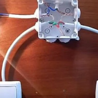
The main task during the installation of the PV is the correct connection of the cables in the junction box. It must be large enough to accommodate a minimum of 16 wires. If you do the work slowly and ring all the connections with a multimeter, you will end up with a workable electrical circuit.
Option # 2 - three-zone placement
Independent three-zone control of two lighting circuits differs from the two-zone considered above by the presence of a special cross switch. It is located exclusively in the middle of the electrical circuit, although it has the same functionality as the other two DPVs.

The double crossover switch has an unusual design containing a transit contact. One of the wires coming from the first switch is always connected to it, regardless of the position of the toggle switch. It closes in both positions of the cross-flow RPV, which ensures the functioning of the entire electrical circuit.
The middle crossover is not interchangeable with end devices. An infinite number of such intermediate devices can be added to the considered circuit, increasing the number of zones for turning on / off the light in the room. But the complication of the circuit leads to an increase in the number of necessary wires and strobe in the walls, which will not add joy when you independently install the wiring.

To install an additional DPV, it will be necessary to make another groove for cable routing from the distribution box. It needs to fit as many as 8 cores: 4 going from the first switch and 4 going to the second.
If electricians are laid by professionals and there is a financial opportunity to install all the switches, then using an RPA with three-zone control for this is an excellent option.
Junction box installation
All wires during the installation of the DPV must be concentrated in the junction box. This will reduce the number of strobe and simplify the maintenance of wiring in case of a change in the number of fixtures or their switching scheme.
Preferably post distribution box between two limit switches at the level of the lighting fixture located in the center of the room. However, the final choice of the installation location is based on the specific configuration of the room and the features of the placement of the elements of the electrical circuit.

The worst option for connecting the wires in the distribution box is the usual twist with electrical tape. This method can lead to heating of the insulation and subsequent fire.It is best to connect the cores with the help of special terminals, because they provide ease of installation and subsequent maintenance.
Procedure for installing RPA
The independent installation of a two-gang switch through passage requires not only preliminary theoretical preparation, but also knowledge of the algorithm for installation work. It is important to do all the processes in one pass, without redoing anything due to missing any stage. Next, step-by-step installation instructions for a dual-zone RPA will be described.
Step # 1: design. At this stage, the following actions are carried out:
- A general electrical circuit is drawn.
- The location of the junction box is determined taking into account the maximum savings on the length of the wires.
- The footage of the necessary electrical cables and their type are calculated.
- The location of the switches is determined taking into account ease of use.
- The type of installation is selected: hidden or open (in boxes).
You can design the placement of the DPV yourself on a sheet of paper. Problems should not arise, because detailed similar schemes are on the Internet.
Step # 2: purchase cables, switches, junction box elements. It is better to purchase stranded wires so that it is convenient to bend them in the socket.

Step # 3: junction box installation. It is from her that it is necessary to begin to lead the wire to the rest of the devices. The distribution box is located 15-30 cm from the ceiling in a conspicuous place. Connect it to the mains only after the complete assembly of the entire system.
Step 4: installation of sockets and preparation of fixtures for lighting.
Step 5: measure cable lengths between the points of the electrical circuit and cutting off the necessary pieces. In this case, it is necessary to make a margin of 10-15 cm for connecting each device. The wires are placed in the corrugation or cable channels, so that during floods and wallpapering, they are not exposed to moisture.

Step 6: cable connection, distribution boxes, switches and fixtures in a single system. On the back of the DPA, the wiring diagram should be shown, which must be observed. At the end, you need to use a multimeter to check the performance of all elements of the system.
The metal parts of the fixtures must be grounded. Neglect of this requirement can lead to electric shock. In addition, the “zero”, and not the “phase” should go directly to the lighting devices.
Step 7: power connection and testing.
If the system check was successful, you can disconnect the apartment from the electricity and start redecorating: close the strobes, close the distribution box.
Following the described algorithm will avoid installation errors and execute it quickly.
Conclusions and useful video on the topic
These videos demonstrate the operation of the walk-through switches in a real environment, allowing you to evaluate the convenience of their operation.
The video shows the connection diagram of the through-switch from three places:
Wiring diagram for the two-gang switch:
Interactive work scheme of a two-zone two-key pass-through switch:
It is not difficult to independently connect two-gang walk-through switches in the house. In this case, it is important to strictly observe the connection diagram and follow the described algorithm of actions. The result of successful work will be the money saved on electricity and the comfort of residents when adjusting lighting.
Do you have any personal experience installing two-gang walk-through switches? Please give practical advice to beginner home masters.Tell the subtleties of installation that are known only to you. Leave your comments in the block under the article.
 How to choose a passage switch: device and purpose of various types + marking
 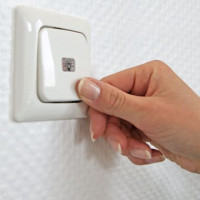 Cross circuit breaker: purpose and device + wiring diagram and installation
 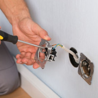 How to connect a passage switch: circuit analysis + step-by-step connection instructions
 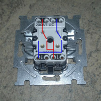 Rocker switch: marking, types, connection features
  How to connect a double switch to two bulbs: schemes + connection tips
 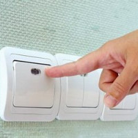 How to install a light switch: step-by-step instructions for connecting typical switches
  How much does it cost to connect gas to a private house: the price of organizing gas supply
  The best washing machines with dryer: model rating and customer tips
  What is the color temperature of light and the nuances of choosing the temperature of the lamps to suit your needs
  Replacement of a geyser in an apartment: replacement paperwork + basic norms and requirements