How to make a ground loop in a private house with your own hands: grounding schemes and installation instruction

The construction of a country house includes a lot of electrical work. Among them, planning and arrangement of the grounding system, which cannot be ignored for safety reasons and the requirements of the PTEC, is not the least.
Doing grounding in a private house with your own hands is not prohibited, therefore, in this material we will consider in detail the main stages of the design and installation of the circuit.
The content of the article:
The meaning and need for grounding
The energy supply of a private house is based on the electric network, which is dangerous for residents, if some measures are not taken to eliminate it. Such measures include double insulation of conductors, equalization of potentials, RCD installation and difavtomatov.
Grounding of the power supply network also plays an important role and is intended to divert the electric current that has appeared in the wrong place to the ground.

One piece of reinforcement or profile clogged into the ground is not enough. Grounding is a whole system of interacting elements connected with other systems.
It cannot be mounted without picking up the parts that are suitable for the parameters and without making preliminary calculations.

Between urban high-rise buildings and private housing there is a difference in the arrangement of grounding systems.
In apartment buildings, the bus is located in a floor electrical panel, while for a private house, the ground loop is literally buried in the ground, since it is located nearby and does not require much effort for installation.
All requirements for the design and installation of the grounding system are set out in PTEEP 2.7.8. The owner of the house should know that the commissioning of the independently equipped structure will be carried out by the organization-supplier of electricity.
Its representatives are required to visually inspect the ground visible parts of the system once every six months, and about once every 12 years to excavate and check the condition of the underground elements.
System selection and mapping
There are three grounding systems in total: TT, IT, TN, of which the latter is divided into three more varieties - TN-S, TN-C, TN-C-S.
In private housebuilding, TN-C-S or TT system circuits are usually used, and TN-C-S looks more attractive, since there are less requirements for its installation.

The system starts from the main grounding bus, which is installed either in the electrical panel of the house or in the cabinet of the input device.
The most rational decision is considered when the grounding is located on a support redirecting the electric main to the house.


TT system is used much less frequently. Representatives of the energy supplying organization are engaged in it, and if the owner nevertheless decides to save money and independently install, then the same employees of Energosnab will come to certify the documents.
If you still take a chance and choose a TT grounding scheme for a private house, then do not forget about the mandatory RCD installation!
Grounding Installation Instructions
There are two methods for assembling and installing underground grounding structures. The first one can be done on your own, although you will have to work hard and spend a lot of time, and the second is only for professionals, since you will need special equipment and skills to measure resistance.
Option 1 - ground wire + ground electrode
First, we will consider how to independently make grounding in a private house, without resorting to paid services. The system consists of two main elements, each of which is selected depending on the installation conditions.
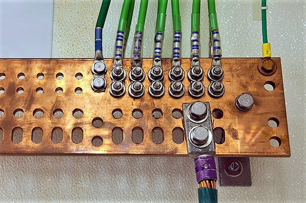
Ground wire - a copper conductor with a cross section equal to that of the phase core. It is connected at one end to a bus located in the electrical panel, and at the other end to a grounding conductor buried in the ground. Grounding conductors from all electrical installations in the house also lead to the bus.

Earthing switch - This is a structure made of steel elements that is in close contact with the ground and serves to equalize potentials when voltage appears.
When designing, take into account the parameters of soil resistance, calculate the dimensions of the rods and frames, as well as the depth.

There is a universal design, for the creation of which there is no need to make complex calculations.
To make it, you will need:
- three 3-meter corners 50 * 50 mm or a steel pipe with a wall of 3 mm and a diameter of 16 mm;
- three 3-meter corners 40 * 40 mm.
Also need welding machine, cutting tools, sledgehammers, fixing materials, and for earthworks - a shovel and a bucket.
Step-by-step instruction:
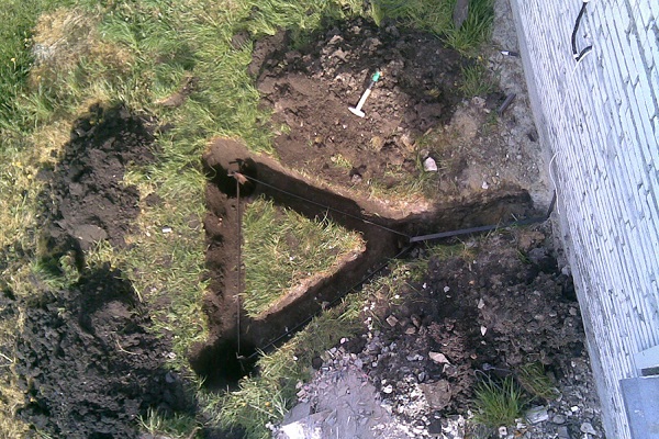
- We dig a trench from the house to the installation site of the ground electrode system. Its depth and width are about half a meter.
- We make markings for driving in pins (corners) in the form of an equilateral triangle with a side of 3 m.
- In places of the vertices of the triangle we dig holes in the depth of 50 cm.
- We connect the pits with narrow grooves around the perimeter to make a triangle.
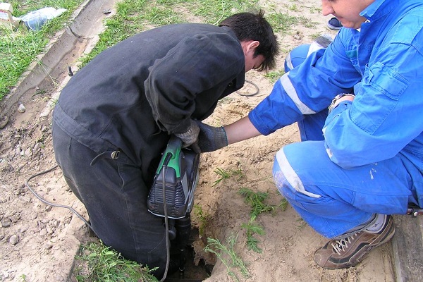
- We hammer the corners 50 * 50 into the ground so that parts of a length of about 0.2 m remain above its surface.
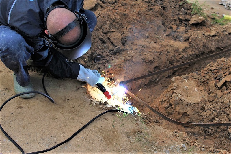
- We weld three corners 40 * 40 in the shape of a triangle.
- We weld a triangle to the corners hammered into the ground.
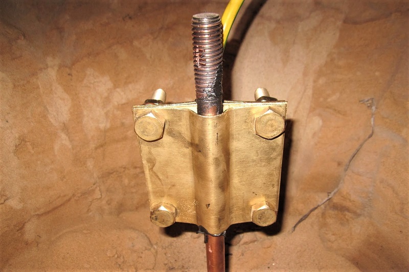
Then we connect the grounding conductor to the structure: we press in its end with a round tip and, using a suitable size bolt, fasten it to the hole drilled in one of the corners.

Metal parts must be covered with soil, preferably sand, and the place of installation of the ground electrode and conductor should be marked with a sign so that during construction or economic work it will not be damaged.
Recommendations for the selection of parts and installation of the ground electrode system in the ground:
For steel rods and the strip connecting them, edible salt is dangerous - it corrodes the metal and renders the structure unusable. Make sure that this substance does not accidentally get into the ground near the ground electrode system.
Option 2 - Modular Pin System
If the construction of metal parts can be done by yourself, then the factory pin must be purchased at the store.
Its main advantage is the absence of labor-intensive excavation and welding, and the disadvantage is the additional cost of paying for the services of a service organization.


In a home-made design, the area of contact with the soil increases due to the use of several corners.There is only one pin, so the increase in contact occurs due to its length. The device is driven into the ground to a depth of 20-40 m.
Earthwork is reduced to pulling out one hole with dimensions of 0.5 * 0.5 * 0.4 m. It is not recommended to use a hammer drill to hammer a pin, since rotation of the pin head should be excluded. Here you need a hammer with a special nozzle.
In the factory kit, together with the pin, there is a clip for attaching the ground conductor, so the installation process consists in driving the main device and connecting it to the wire.

There are standards that should be followed during installation:
- for 3-phase 380 V - resistance no more than 2 Ohms;
- for 1-phase 220 V network - resistance no more than 4 Ohms.
With self-assembly, to ensure safety before the inspection bodies, it is better to accurately calculate the level of groundwater and make sure that the ground electrode drops to this level.
Upon contact with groundwater, the resistance parameters will return to normal.
Conclusions and useful video on the topic
DIY grounding device experience:
Practical tips for installing a factory made earthing switch:
Installation of an earthing system of several rods:
As you can see, you can install the grounding system yourself, so using a team of invited electricians - the first way is cheaper, but more complex, the second is expensive, but reliable.
However, the main thing in competent installation is the result that should make the power grid of the house completely safe for its owners.
Do you have any questions about making your own ground loop? Ask them below under the article - our experts and competent site visitors will try to help you.
If you notice inaccuracies or errors in the above material, or want to add useful information to the article, please write to us in the comments section.
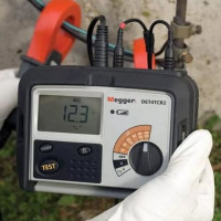 Earth resistance measurement: a review of practical measurement methods
 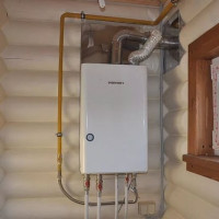 How to make grounding for a gas boiler: grounding requirements and installation instructions
  Grounding the bath in the apartment: why and how to properly ground the bath
  How much does it cost to connect gas to a private house: the price of organizing gas supply
  The best washing machines with dryer: model rating and customer tips
  What is the color temperature of light and the nuances of choosing the temperature of the lamps to suit your needs
  Replacement of a geyser in an apartment: replacement paperwork + basic norms and requirements
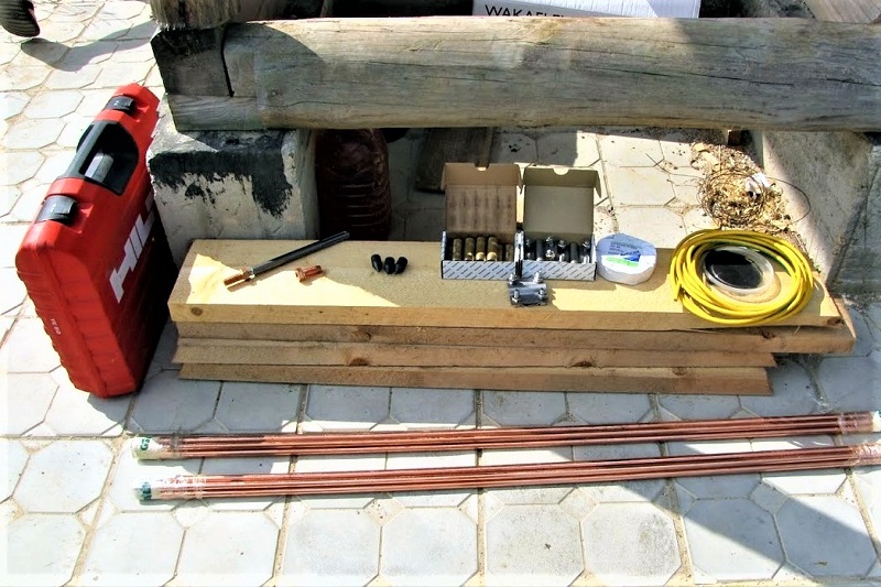
Good day! I plan to build a country house with an area of more than 100 square meters. meters. Initially, I did not plan to mount the ground loop (our fathers did fine without it), but my wife insists on installing a down conductor structure. In this regard, I am interested in the following information. How does the area of an electrified object affect the design of the ground loop? Can a paved area be placed on top of an installation in the ground? Will there be problems with the fire brigade when checking the premises, if you still do not install grounding?
Good afternoon, Victor. In order of questions:
1. Your area of 100 square meters is not enough for designers to think about an atypical grounding design. The article has a block beginning with the words, "There is a universal design ..." - re-read it again. It's all about grounding materials.
2. The linear grounding structure, located near the foundation of the house, will remove the problem of hard coating.
3. Fire supervision is interested in its issues, but Rostekhnadzor, if the electric power of the house exceeds 15 kW, will carefully study the design of the house, grounding. Attached is a screenshot of the correspondence of a citizen with Rostekhnadzor employees - a very useful material for you.